Periodic tasks with seL4
In a nutshell
In this article, I explain how to implement periodic tasks in seL4, a design pattern used in many embedded, safety-critical systems. This sounds probably very basic but using periodic tasks with non-blocking communication mechanisms is really helpful to ensure that your system will continue to work and meet its deadline. Please not that it does not mean that it works correctly, it just guarantees some important timing and behavioral characteristics.
Context
I started using the seL4 micro-kernel since few months. For those who do not know what is seL4, this is a formally verified kernel. Formally verified means that seL4 services are correctly implemented. It does not mean that the services are correctly configured and used, which is another story (more on that in a further article).
The micro-kernel itself provides only very few services, mostly: TCB, endpoints and other communications services. Nothing more, especially time or scheduling. Device drivers are also implemented in user-space, meaning that partitions must require access to the hardware and manage it appropriately.
Also, writing code for seL4 is hard. Really hard. You have not only to understand the services but also use the API and do the right function calls with the appropriate arguments. Trust me, it is a real pain. In order to overcome these issues, the NICTA team developed a specific ADL, CAmkES.
Issue with seL4 and periodic tasks
As mentioned before, seL4 does not provide any timing service. It provides a service to schedule threads (using a Round-Robin policy with priorities) but does not provide anything to wait or be activated at a given period.
So, if you are looking for something like pthread_cond_timedwait() or just sleep() (which is NOT real-time friendly by the way), you will feel out of luck.
To overcome this issue, you must design your own timing service in a process that will ultimately activate the other tasks.
Implement a timing service
We will implement a timing service with CAmkES. The timing service will define a hardware component (hardware timer) and a time manager that will activate the tasks according to their periods.
In the following example, we will have two periodic tasks: one is activated every second while the other one is activated every two seconds. We will then define four components:
- The hardware component that abstracts the hardware platform
- The time manager that manages the hardware components and send a signal to activate the other tasks. One signal will be sent every second, another every two seconds
- One task connected to the first signal (activated every second)
- One task connected to the second signal (activated every two seconds)
We will illustrate that with the x86 platform.
Defining the CAmkES components
The overall architecture is defined below. The CAmkES hardware component models your time, what will give you the concept of time. On the x86 architecture, there is the old PIT that provides the concept of time. We will use it then. For more information about how it works, you can read the description on osdev or wikibooks
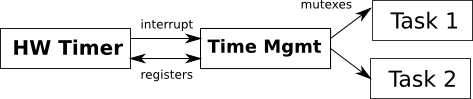
The timer components and timer managment in CAmkES are defining like the following (Timerbase being the hardware component and Timer the time manager)
component Timerbase {
   hardware;
   provides IOPort command;
   provides IOPort channel0;
   emits PITIRQ irq;
}

component Timer {
  uses IOPort   pit_command;
  uses IOPort   pit_channel0;
  has mutex     timer;
  consumes DataAvailable  irq;

  emits sig Hello1_Thr_activator;
  emits sig Hello2_Thr_activator;
}
The Timerbase component accesses two IOPort that are hardware register/memories used to control the timer. This is architecture-dependent and related to the PIT. The irq corresponds to the interrupt sent by the system.
Now, let’s define the application component (application task). We call it HelloThreadImpl. This task is a control task that will consumes a signal that activates it.
component HelloThreadImpl
{
  control;
  consumes sig activator;
}
Then, we need to create an assembly that integrates and configures all components. The assembly corresponds to the components configuration showed in the picture before.
import <std_connector.camkes>;
import "components/timer/Timer.camkes";
import "components/HelloThreadImpl/HelloThreadImpl.camkes";
assembly {
  composition {
    component Timerbase timerbase;
    component Timer timer;


    component HelloThreadImpl Hello1_Thr;
    component HelloThreadImpl Hello2_Thr;

    connection seL4Notification notification0
     (from timer.Hello1_Thr_activator, to Hello1_Thr.activator);
                connection seL4Notification notification1 (from timer.Hello2_Thr_activator, to Hello2_Thr.activator);

    connection seL4HardwareInterrupt timer_irq
      (from timerbase.irq, to timer.irq);

    connection seL4HardwareIOPort pit_command
      (from timer.pit_command, to timerbase.command);

  connection seL4HardwareIOPort pit_channel0
      (from timer.pit_channel0, to timerbase.channel0);
  }

  configuration {
    timerbase.irq_attributes = 0;
    timerbase.command_attributes = "0x43:0x43";
    timerbase.channel0_attributes = "0x40:0x40";
  }
}
We define the timer component (one of type Timerbase and one of type Timer) as well as two software components. The connections notification0 and notification1 are the one that will activate the tasks through a signal, to notify them that they can be activated.
In the configuration section, the hardware component is configured. This part is architecture-dependent and if you are planning to use such a pattern on another architecture, you would need to adapt the hardware component specification and its relative configuration section.
Implementing the code
Now, we need to implement the Timer and the HelloThreadImpl components.
For the timer, there is a part that is architecture-dependent and another that is generic and activates the tasks. We will skip the architecture-dependent part, you can look at it in the code by yourself. The most interesting part is in the interrupt handler.
In the driver interrupt handler, we get the current time in milliseconds. Then, depending on the value, we send a signal to activate a task. In the following code, we send a signal to the first task every 1000 ms and send a signal to the second task every 2000 ms.
void irq_callback(void *_ UNUSED)
{
  timer_handle_irq(timer_drv, 0);

  uint64_t ms = current_time_ms();

  if ( ( ms % 1000) == 0)
  {
    Hello1_Thr_activator_emit();
  }

  if ( ( ms % 2000) == 0)
  {
    Hello2_Thr_activator_emit();
  }

  irq_reg_callback(irq_callback, NULL);
}
Let’s have a look at the HelloThreadImpl code now. It should be pretty obvious with an infinite loop waiting for a signal and executing a piece of code. The code is provided below.
#include <camkes.h>

#include <generatedtypes.h>
#include <stdio.h>
#include <string.h>

void user_hello_spg ()
{
  printf *"HELLO\n");
}

int run(void)
{
  while (1)
  {
    activator_wait();
    user_hello_spg ( );
  }
  return 0;
}
Getting the code & run it
The code is availabe there
If you want to run it:
- Check out CAmkES and make sure it works on your system. To get started, have a look on the instruction on the seL4 wiki
- Get the code here
- decompress the archive into the
apps/directory of the CAmkES installation - Edit the
Kconfigfile at the root directory of your CAmkES installation and add in theApplicationssection the following line:source "apps/twotasksx86instance/Kconfig" - invoke
make ia32_simple_defconfig - invoke
make oldconfig - invoke
make - If everything compiles fine, it means that a simple example for the ia32 platform works. We can then compiles the example from this article
- Invoke
make menuconfig. In the menu, in theApplicationssection, unselect all examples and selectGenerated CAmkES TwotasksX86Instance application - exit the configuration tool and save the changes
- invoke
make - simulate the system with qemu by invoking
qemu-system-i386 -nographic -kernel images/kernel-ia32-pc99 -initrd images/capdl-loader-experimental-image-ia32-pc99
When running the code, you should just see that you get more output every two seconds. Basically, every second, you get two HELLO message on the console while every two seconds, you see two messages.
Issues & limitations
In this post, I tried to explain how to use seL4 and its related ADL in order to implement a popular design pattern for safety-critical systems: a periodic tasks. As seL4 provides very minimal services and as no built-in timing service, you must define them yourself.
Beyond that, one can notice that there is some issues with such an approach. First of all, it assumes that the system is schedulable and that all tasks will complete their job and will not interfere with the execution of the other tasks. If one task that is at a high priority takes all the CPU (in other word, if the code in user_hello_spg contains an infinite loop), your system will be stuck. One workaround would be to use the concept of domains in seL4 but unfortunately, it does not seem that CAmkES exports it to the user. Also, the system does not enforce any timing budget. The NICTA team is working on some real-time extensions that might provide such services.
Note: You might find some error/bugs in the code, this is mostly done for educational purposes. If you find any issue/bug, do not hesitate to contact me.